|
|
Definitive model of disk-float-type valve with compact float and tank
|
|
Multi-functional with liquid level regulation, constant flow regulation
(UFSF-C type), and automatic shutoff of the flow when the liquid level
reaches the upper limit.
|
|
For general use:
|
UFSF-S type (Standard type)
|
|
For constant flow regulation under any condition:
|
UFSF-C type (Full range constant flow regulation type)
|
|

|
Compact float and compact tank
|
|
The unique balancing mechanism enables secure liquid level control using
a compact float regardless of the inlet pressure, and allows the float
tank to be a significantly compact size.
Also, due to this balancing mechanism, the valve operation is very smooth,
causing no water hammer.
|
|

|
Complete water shutoff possible
|
|
Due to the balancing mechanism, an automatic self-closing force develops
near the closing of the valve, which not only allows for use of a compact
sized float, but also provides complete water shutoff performance.
|
|

|
Durability and maintenance-free
|
|
Due to its simple construction, the valve is clog-resistant, durable and
practically maintenance-free.
|
|

|
Full range constant flow regulation (UFSF-C type)
|
|
Constant flow regulation is performed over the entire range even when the
inlet pressure fluctuates. Excessive replenishment of water is therefore
prevented even when the inlet pressure is high, enabling balancing of water
supply among water distribution works, farm ponds, and other. Wasteful
use of water resources can be prevented by setting the minimum necessary
flow rate.
The set flow rate can be changed when necessary with the maximum flow rate
adjustment screw, enabling the water supply quantity to be changed according
to season.
|
|

|
Demonstrated performance
|
|
Excellent performance as verified by the National Institute for Rural Engineering.
|
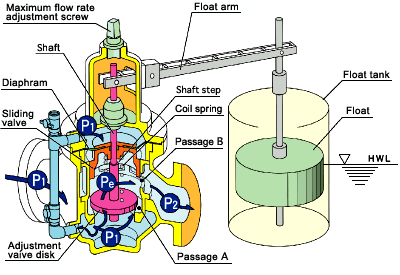
Structure & Principle (PAT.)
UFSF-C type (Full range constant flow regulation type)
|
|
 |
|
1.
|
When the float begins to ascend as the liquid level in the float tank rises,
the shaft is pushed down, narrowing passage A around the adjustment valve
disk. This reduces the flow rate and intermediate pressure Pe begins to
drop.
|
|
2.
|
Accordingly, the sliding valve is pushed down by inlet pressure P1 that
acts on the top of the diaphragm, thereby narrowing passage B and causing
intermediate pressure Pe to be restored to the original pressure. The differential
pressure between the front and the rear of the adjustment valve disk is
therefore maintained at a constant value and the valve can be opened and
closed very easily regardless of the inlet pressure.
|
|
3.
|
As the liquid level continues to rise, the sliding valve is pushed down
further, ultimately coming in contact with the shaft step and is integrated
with the adjustment valve disk via the shaft, thus causing inlet pressure
P1 acting on the bottom of the adjustment valve disk to become balanced
with inlet pressure P1 acting on the top of the diaphragm.
|
|
4.
|
As a result, the axial thrust of the valve shaft balances, allowing the
valve to be opened and closed very easily and realizing secure water shutoff
with a compact float. (The length of the float arm may thus be made short,
which reduces installation space and costs).
|
|
5.
|
When the liquid level drops, the valve acts sensitively in response to
the movement of the float and begins to supply water. The adjustment valve
disk becomes fully open when the liquid level drops further. Since the
valve itself has a constant flow regulating mechanism, a stable flow rate
is maintained even if the inlet pressure fluctuates.
|
|
6.
|
Water discharge is moderate and quiet due to the effective pressure reducing
mechanism with the interaction of the adjustment valve disk and the sliding
valve. The float tank can be made significantly compact in comparison to
conventional valves, achieving a reduction of construction space and costs.
|
|
Flow rate characteristics
UFSF-C type (Full range constant flow regulation type)
|
|
|
Constant flow rate characteristics at each set flow rate S (float valve
opening %) |
|
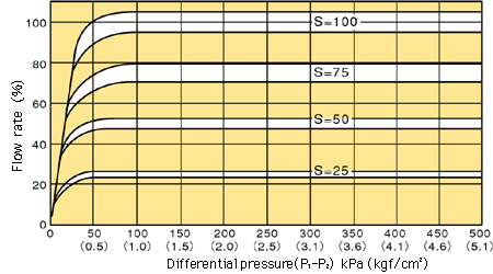 |
This UFSF-C type valve prevents over-discharge by adjustment of position
S (stroke %) of the maximum flow rate adjustment screw, and a stable constant
flow rate is maintained across the entire range regardless of the fluctuation
of the inlet pressure.
The constant flow regulation is securely maintained even at a low flow
rate; thus allowing the minimum necessary flow and preventing wasteful
use of water resources.
UFSF-S type (Standard type) does not have the same constant flow regulation
mechanism as the UFSF-C type, but it is equipped with the same shaft thrust
balancing mechanism, enabling complete water shutoff with a compact float.
This UFSF-S type also has a feature that allows maximum supply of water
in accordance with the inlet pressure, and desired characteristics may
be set by adjusting the position of the maximum flow rate adjustment screw. |
Example of pipeline system
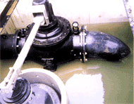
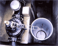
Example applications
|
 |
 |
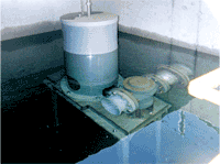 |
|
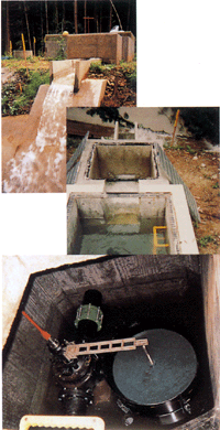
Sumoto Land Improvement Office in Hyogo Pref. |
|
|
Takaoka Agricultural Land and Forestry Office in Toyama Pref. |
|
|
Seibu Agriculture and Forestry Office in Shizuoka Pref. |
|
| UFSF-500 |
UFSF-300 |
UFNF-100 |
|
|
|
|
Adopted in the 1997 New Technology Introduction Project
by the Tohoku Agricultural Administration Bureau
|
|
As an alternative, depending on site conditions, Liquid Level Regulator
Valve, employing ball taps, is also available.
For details, please refer to Pilot-Type Regulator Valves (Overview).
|
|
Selection chart & Outer dimensions
Specifications/Performance
|

|
Inlet pressure (Primary pressure):
|
Max. 1MPa (For JIS 10K standard)
|
|

|
Applicable liquid:
|
Various liquids at temperatures of 0-70 degree C (Please inquire for special
liquids.)
|
|

|
Flow rate accuracy of UFSF-C type:
|
+/- 10%
|
|

|
Flange standard:
|
JIS 10K, JIS B2062 Waterworks standard
|
|

|
Material
|
(Valve case/Valve disk):
|
FC/SUS, FCD/SUS
Besides the above, a wide variety of materials are available, such as YOKOTA's duplex type stainless steel YST130N with high corrosion resistance.
|
|
|
(Float):
|
FRP
|
|

|
Cavitation characteristics:
|
The allowable cavitation coefficients (cc) are:
With a bore less than 100mm: cc=0.45
With a bore more than 150mm: cc=0.24
For details, please refer to this page.
|
Selection chart
|
UFSF-S type (Standard type)
|
 |
|
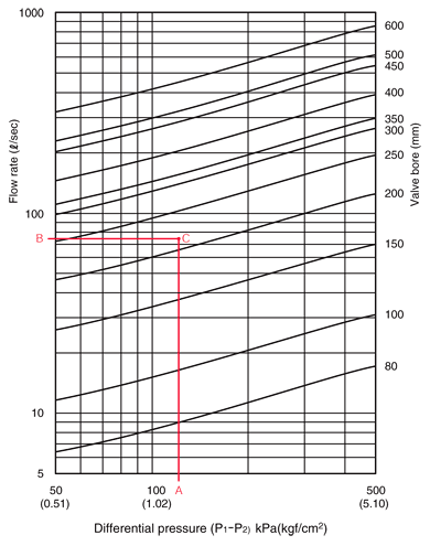
How to use the selection chart
|
|
Plot point C with x-axis value A and y-axis value B, where A is a planned
differential pressure between the front and the rear of the valve, and
B is a planned flow rate. Then select a valve with a bore size line immediately
above point C.
In the example on the left, a 250mm bore valve is selected.
|
|
Note:
|
|

|
The selection chart is based on the maximum flow speed of 3m/sec. If a
planned maximum flow speed exceeds this level, please contact us.
|
|

|
The flow rate set by the maximum flow rate adjustment screw should be more
than 10% of the maximum flow rate.
|
|
UFSF-C type (Full range constant flow regulation type)
|
Bore
mm
|
Model No.
|
Maximum flow rate
|
Standard
pressure type
|
Low
pressure type
|
|
(m3/min)
|
(l/sec)
|
(m3/min)
|
(l/sec)
|
|
80
|
UFSF-080C
|
0.36
|
6
|
0.24
|
4
|
|
100
|
-100C
|
0.66
|
11
|
0.36
|
6
|
|
150
|
-150C
|
1.50
|
25
|
0.90
|
15
|
|
200
|
-200C
|
2.64
|
44
|
1.50
|
25
|
|
250
|
-250C
|
3.90
|
65
|
2.28
|
38
|
|
300
|
-300C
|
6.00
|
100
|
3.60
|
60
|
|
350
|
-350C
|
6.60
|
110
|
3.96
|
66
|
|
400
|
-400C
|
8.70
|
145
|
5.10
|
85
|
|
450
|
-450C
|
12.90
|
215
|
7.50
|
125
|
|
500
|
-500C
|
13.80
|
230
|
8.10
|
135
|
|
600
|
-600C
|
19.20
|
320
|
11.40
|
190
|
|
|
Note:
|
|

|
The flow rate set by the maximum flow rate adjustment screw should be more
than 10% of the maximum flow rate.
|
|

|
The model No. for low pressure type valves is followed by "L".
(e.g. UFSF-200CL)
|
 |
Operating differential pressure
Standard type: 50-500kPa
Low differential pressure type: 20-200kPa |
|
Outer dimensions/Installation dimensions
|
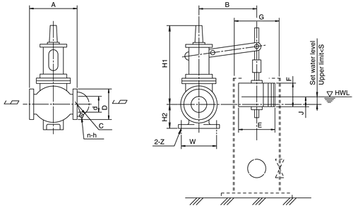
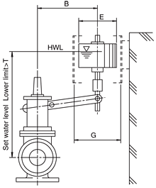
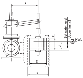
Independent float tank type (The adjustment plug key and the float tank
are optional accessories.)
|
|
|
|
Submerged type
|
Integrated float tank type (Bore: 150mm or less)
|
|
|
|
|

|
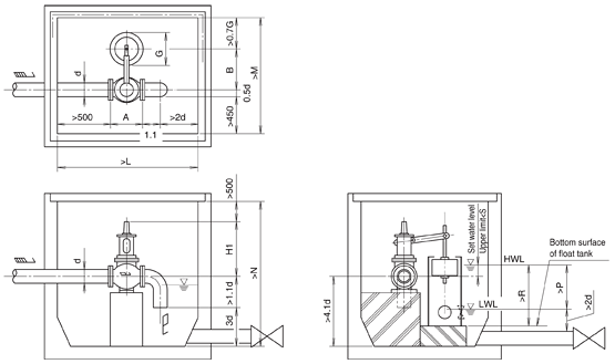
The dimensions indicated in the drawings are minimum dimensions which take
into account required maintenance such as assembly and disassembly and
refer only to cases where there is a farm pond adjacent to the valve chamber.
If an independent valve chamber is added to a pipeline (i.e. there is no
farm pond adjacent to the valve chamber), depending on flow conditions,
there may be rapid fluctuations in water level in the float tank, causing
water hammer at the front or the rear of the valve chamber. Therefore avoidance
of such water hammer should be considered in deciding the size of the valve
chamber. For deciding its size, it is recommended to refer to guidelines
such as "Pipeline Design Manual" supervised by the Ministry of
Agriculture, Forestry and Fisheries of Japan. If you need more help, please
contact us.
|
|

|
Since leg parts are not provided for valves with a bore of 150mm or less,
please support those valves with the piping.
|
|

|
If air is sucked into the outflow pipe of the valve chamber, a partition
plate should be installed and the valve's discharge opening should be placed
below the lowest water level.
|
|

|
To mount the float tank, please affix it to the side wall of the chamber
with a band, or, if placing it on the bottom of the chamber, provide a
passage hole at the lower part of the float tank.
|
|

|
Since the float can be attached on either the left or right side of the
flow direction, please specify when making an inquiry.
|
|

|
To simplify installation, a unit with the valve preinstalled in a box culvert
can be provided. Please inquire.
|
Bore
d
|
Model
No.
|
Dimensions
|
Mounting
|
Weight
of
main
body
(kg)
|
Flange
(Waterworks standard)
|
Valve chamber
(minimum dimensions)
|
Set water
level
|
|
A
|
B
|
H1
|
H2
|
E
|
F
|
G*
|
J
|
W
|
Z
|
D
|
C
|
n-h
|
L
|
M
|
N
|
P
|
R
|
S
|
T
|
|
80
|
UFSF-080
|
280
|
440
|
550
|
95
|
420
|
200
|
442
|
170
|
-
|
-
|
35
|
211
|
168
|
4-19
|
1030
|
1240
|
1380
|
280
|
400
|
10
|
750
|
|
100
|
100
|
350
|
480
|
570
|
127
|
420
|
300
|
442
|
220
|
-
|
-
|
80
|
238
|
195
|
4-19
|
1160
|
1290
|
1480
|
290
|
400
|
10
|
800
|
|
150
|
150
|
450
|
630
|
635
|
153
|
565
|
300
|
592
|
240
|
-
|
-
|
120
|
290
|
247
|
6-19
|
1415
|
1570
|
1750
|
550
|
700
|
30
|
920
|
|
200
|
200
|
600
|
740
|
690
|
220
|
670
|
450
|
700
|
360
|
320
|
23
|
230
|
342
|
299
|
8-19
|
1720
|
1780
|
2010
|
690
|
850
|
100
|
1100
|
|
250
|
250
|
700
|
850
|
850
|
250
|
670
|
450
|
700
|
380
|
500
|
23
|
380
|
410
|
360
|
8-23
|
1975
|
1915
|
2375
|
780
|
950
|
200
|
1200
|
|
300
|
300
|
800
|
950
|
885
|
295
|
760
|
500
|
800
|
390
|
440
|
23
|
500
|
464
|
414
|
10-23
|
2230
|
2110
|
2615
|
800
|
1100
|
240
|
1300
|
|
350
|
350
|
900
|
1000
|
960
|
305
|
760
|
500
|
800
|
400
|
480
|
23
|
590
|
530
|
472
|
10-25
|
2485
|
2185
|
2895
|
920
|
1150
|
280
|
1400
|
|
400
|
400
|
1000
|
1150
|
1040
|
320
|
855
|
500
|
900
|
410
|
660
|
25
|
800
|
582
|
524
|
12-25
|
2740
|
2430
|
3180
|
970
|
1200
|
280
|
1500
|
|
450
|
450
|
1100
|
1300
|
1240
|
450
|
935
|
550
|
1000
|
430
|
600
|
27
|
1200
|
652
|
585
|
12-27
|
2995
|
2675
|
3585
|
1000
|
1300
|
350
|
1800
|
|
500
|
500
|
1200
|
1300
|
1240
|
450
|
935
|
550
|
1000
|
430
|
600
|
27
|
1300
|
706
|
639
|
12-27
|
3250
|
2700
|
3790
|
1000
|
1300
|
350
|
1800
|
|
600
|
600
|
1400
|
1400
|
1435
|
500
|
1030
|
800
|
1100
|
700
|
700
|
27
|
2300
|
810
|
743
|
16-27
|
3760
|
2920
|
4395
|
1300
|
1600
|
400
|
2200
|
|

|
The dimension G indicates the inner diameter of the float tank.
|
Specifications stated here may be subject to change without notice due
to product improvement.
|
|