|
Small tank, but no severe, intermittent operation
YOKOTA Mini-Tank Automatic Water Supply Equipment
|
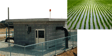
| The tank is small and placed in the building. |
|
Widely adopted in Kobe district irrigation equipment projects
The irrigation system spreads across fields from Kobe City's West to North
Wards and has been used continuously since 1970.
When the end valve at the field is opened, river or pond water is supplied
through the pipeline. Use of water for agricultural purposes has been made
as convenient as twisting open the faucet on a regular tap water supply.
Moreover, construction and maintenance of agricultural irrigation ditches
is unnecessary resulting in extremely low loss of water resources.
The pipeline network includes over 60 pumping stations using YOKOTA's Mini-Tank
Automatic Water Supply Equipment.
The "Mini-Tank Automatic Water Supply Equipment" is an automated
system based on technology developed by our company. The feed pump activates
when the pressure switch built into the mini-tank is turned on, and deactivates
by the No-Feed Detector built into the check valve in the water pipe. Because
it is a completely hands-off automated system, use of river and pond water
has been made as convenient as simply "turning on the tap".
Special features of the YOKOTA Mini-Tank Automatic Water Supply Equipment
|

|
Extremely small pressure tank
|
|

|
No severe, intermittent pump operation
|
|

|
Air supply to the pressure tank is unnecessary
|
|

|
No water-hammer when the pump is stopped
|
|

|
Excellent pump self priming
|
|

|
High resistance to pipe burst from winter freezing
|
|

|
Complete hands-off automatic operation
|
A good feature of our "YOKOTA Mini-Tank Automatic Water Supply Equipment"
is the tank size compared with conventional automatic water supply systems.
The YOKOTA mini-tank is surprisingly small at one-tenth the size or less
of conventional systems, but despite the small size there is no severe
intermittent operation. The equipment is favored for its convenience and
minimum space requirements.
You may ask why this is possible. The following comparison chart provides
an explanation.
Comparison with conventional pressure tanks
| |
Conventional pressure tanks
|
YOKOTA Mini-Tank
|
|
Construction
|
|
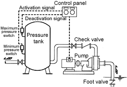
Pump turns on and off by pressure switches.
|
|
|
|
Two pressure switches, maximum/minimum pressure switches, are built into
pressure tank.
|
|
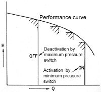
Pump activation is controlled by the minimum pressure switch and deactivation
by the maximum pressure switch. As a result, the internal pressure of the
pressure tank is consistently maintained between maximum and minimum.
|
|
Operation order:
|
|

|
When the end valve is opened, the pressure in the tank lowers due to the
release of the stored water, and the minimum pressure switch activates
the pump.
|
|

|
The pump begins feeding water and the tank's internal pressure rises, which
causes the maximum pressure switch to deactivate the pump. After that,
the pump repeatedly turns on and off so that the internal tank pressure
is maintained between maximum and minimum.
|
|

|
When closing the end valve, the tank's internal pressure rises and the
maximum pressure switch deactivates the pump.
|
The process can be conceptualized as follows: water is supplied from the
tank, and when the stored amount in the tank has been reduced, the tank
is recharged by what is called "indirect flow".
|
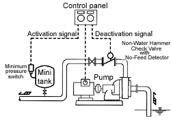
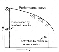
| Pump turns on by pressure switch, turns off by No-Feed Detector device. |
|
|
|
Equipped solely with a minimum pressure switch built into the pressure
tank. A No-Feed Detector for detecting the presence of water flow is built
into the Non-Water Hammer Check Valve in the water pipe.
|
|
Pump activation by minimum pressure switch, deactivation by No-Feed Detector.
|
|
Operation order:
|
|

|
When the end valve is opened, the pressure in the tank lowers due to the
release of the stored water, and the minimum pressure switch activates
the pump. (The similarity to conventional tanks ends here.)
|
|

|
The pump begins feeding water, the tank's internal pressure rises, but
the pump does not stop unless the water feed rate has been lowered extremely
by the closing of the end valve.
|
|

|
The more the end valve closes, the closer the Non-Water Hammer Check Valve
comes to completely closing, upon which the No-Feed Detector deactivates
the pump.
|
The process can be conceptualized as follows: Water is supplied directly
using the pump by what is called, simply, "direct flow", and
when usage ends, the pump stops.
|
|
Pressure tank size
|
Large
Because of a construction that controls pump deactivation through "pressure"
information, if the pump's closing pressure is not set high enough so that
it sufficiently exceeds the tank's maximum pressure, the pump's deactivation
performance worsens, and it may cause a condition where the pump does not
deactivate.
Also, if the pump's operation conditions change as a result of performance
degradation or if there is a water level change on the intake side, it
is necessary to lower the maximum pressure setting so that pump deactivation
is assured.
As a result, the maximum/minimum pressure setting range decreases and the
intermittent operation on a small sized pressure tank becomes more severe.
To avoid these difficulties, pressure tanks have been enlarged for safety
assurance.
|
Extremely small
Due to a precision construction whereby the pump is deactivated by direct
detection of a reduction in water use by the No-Feed Detector, rather than
through indirect pressure information, fluctuation in internal tank pressure
or pump operation conditions have no effect and the pump deactivates smoothly.
Accordingly, there is no severe intermittent operation even with a small
pressure tank, and the equipment lasts a long time.
In principle, it does not matter how small the tank is. As far as practicality
is concerned, for example, installing a 50-litre tank requires only one-tenth
the space or less of conventional ones.
|
|
Air supply to tank
|
Air supply is required when needed.
Because the tank is large, troublesome work such as setting up air supply
equipment or injecting air with a compressor when needed is necessary to
maintain the water supply pressure.
|
Air supply is unnecessary.
Because the tank is extremely small, a standard rubber diaphragm (balloon)
has been integrated in the tank, which is more than sufficient to do the
job.
Accordingly, air supply is unnecessary.
|
|
Check valve
|
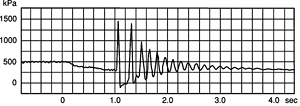
Water hammer occurs.
Because a conventional check valve is used, damage due to water hammer
occurs easily during pump deactivation or unexpected power outages.
|
No worries about water hammer occurrence.
No occurrence of water hammer during pump deactivation or unexpected power
outages based on the movement of the YOKOTA Non-Water Hammer Check Valve
(PAT.).
Moreover, based on the function of the No-Feed Detector, the pump stops
when there is no water-feed (or no occurrence of water hammer) for enhanced
safety.
|
|
Pumping efficiency
|
Suction pumping becomes laborious when suction piping crosses over embankments
or if air is sucked into the system during operation.
For conventional pumps, even if priming water equipment is used, problems
remain with air being sucked into the system during operation and, as a
result, water suction being interrupted. Also, this causes trouble with
water suction if piping crosses over an embankment.
To supplement this lack of self-priming efficiency, a foot valve is generally
installed on the intake side.
However, during the winter when the pump is stopped, water collects in
the piping due to the foot valve, and
pipe burst from freezing occurs easily.
|
No problems with piping across embankments or air being sucked into the
system.
Even if water suction is interrupted by air being sucked into the system
during operation, the system automatically recovers itself because of the
powerful suction force in the YOKOTA Self-Priming Centrifugal Pumps (PAT.).
Moreover, if pumping conditions become more severe such as when piping
crosses over embankments, interlocking a vacuum pump will afford more stabilized
automatic pumping.
Since excellent priming efficiency is provided, there is no need for installing
a foot valve on the intake side.
When the pump is stopped during the winter, water does not remain in the
piping because there is no foot valve. Accordingly,
pipe burst from freezing is nearly non-existent.
|
Self-Priming Centrifugal Pump (PAT.)
|

|
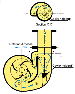
The casing consists of a simple structure made of a semi-double volute
and a cavity holder. This single-suction, single-stage centrifugal pump
displays outstanding pumping performance in a wide range of specifications.
|
|

|
The pump develops maximum vacuum of 60-90kPa (6-9m water column) and displays
outstanding self-priming power.
|
|

|
Low NPSH. Even if cavitation develops due to fluctuations in suction conditions,
this pump can still continue its pumping operation, and therefore does
not require allowance for NPSH.
|
|

|
The pump operates continuously without any problems even if air is sucked
or mixed into the system during pumping operation.
|
|
|
Non-Water Hammer Check Valve (PAT.)
|

|
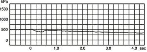
Due to the valve response according to the water flow, there is no delay
in valve closure and water hammer does not occur.
|
|

|
The simple, single-disk construction eliminates breakdowns and maintenance
costs can be reduced considerably.
|
|
|
Pressure change with time after pump operation is stopped
|
|
YOKOTA Non-Water Hammer Check Valve
|
|
Conventional check valve
|
|
|
Cost advantages with the YOKOTA Mini-Tank Automatic Water Supply Equipment
Based on the facts discussed above, significant cost reductions are realized
in the YOKOTA Mini-Tank Automatic Water Supply Equipment as compared with
conventional pressure tanks.
|

|
Low construction cost ...
|
The extremely small tank size requires little space.
|
|

|
Low maintenance cost ...
|
Air supply to the tank is unnecessary. Also, intermittent operation of
the pump is reduced, switch contact points have long-life durability.
|
|

|
Electric cost is the same ...
|
Electric cost is the same whether the tank is large or small. The pump
stoppage time with a large pressure tank is longer, but the supply water
during the pump stoppage is replenished in advance. In effect, there is
no total difference in electricity use as it is a matter of whether electricity
is used beforehand or as needed.
|
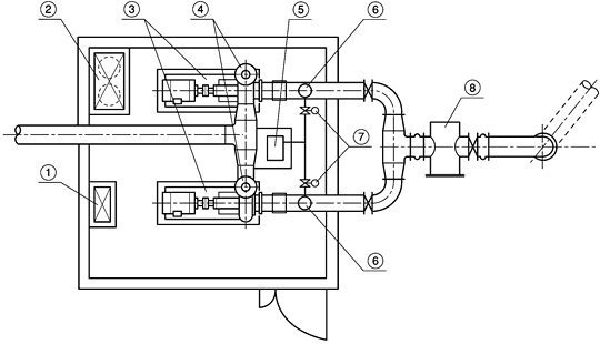
Example applications
|
|
|
|
1. Automatic operation control panel
|
|
2. Self-activation equipment and mini-tank
|
|
3. Water supply pump (Main pump)
|
|
4.
|
No-Feed Detector (Auto-stop equipment)
and Non-Water Hammer Check Valve
|
| 5. Vacuum pump |
| 6. Priming detector |
| 7. Electric motor valve |
| 8. Strainer |
|
|
|
|
Automatic operation procedure
|

|
When the end valve is opened, water stored in the mini-tank is released
and the pressure switch, which detects the decrease in pressure, sends
a signal to activate the vacuum pump.
|
|

|
When the priming detector detects that the suction piping is at full capacity,
it activates the number 1 main pump, water feed begins, and the vacuum
pump stops.
|
|

|
If further water supply is needed, the number 2 main pump activates.
|
|

|
When the end valve is closed, the amount of water passing through the Non-Water
Hammer Check Valve approaches zero. The built-in No-Feed Detector detects
this condition and stops the main pump.
|
Even with the YOKOTA Mini-Tank Automatic Water Supply Equipment, be aware
that if small amounts of water are used intermittently or there is leakage
from the piping, the pump is stopped more frequently.
Actual application
61 pumping stations and 104 pumps (delivered from 1988 to 2003) mainly
in the Kobe area, including the Kobe Minorino Public Corporation River
Improvement Project and Goryoda Pump Facility.
For details of Self-Priming Centrifugal Pump or Non-Water Hammer Check
Valve, please refer to
Self-Priming Centrifugal Pump UHN series
Non-Water Hammer Check Valve SL series
|