|
 |
Mixed-Flow Volute Pump
YM type
Durability and reliability as demonstrated in many power stations
|
|
|
|

|
Large capacity, High head
|
|
Single-suction, single-stage Mixed-Flow Volute Pump with large capacity
and high efficiency, capable of operating near maximum limits.
|
|

|
Handles a variety of liquid properties
|
|
Pump structure allows for selection of suitable parts depending on the
type of liquid, such as chemicals or gypsum slurry, that comes into contact
with them.
|
|

|
Metallic parts
|
|
All parts that come into contact with liquid are metallic and unexpected
problems that result from parts such as rubber linings are avoided.
|
|

|
Reduction of maintenance costs
|
|
Inspection from the coupling side with back-pullout disassembly greatly
reduces costs and frequency of maintenance. (Not available with YM-2510
and YM-3020)
|
|

|
Large selection of materials
|
|
A wide variety of materials are available, including FC, SCS and YOKOTA's corrosion and wear resistant special stainless steel casting (YST), to meet the needs of various kinds of liquid.
|
|

|
Enhanced self-priming is also possible (Optional)
|
|
By interlocking the unique vacuum pump with a water-air separating mechanism
(PAT.), self-priming even with suction piping across an embankment is possible,
which enables automatic pumping operation. (YM-2512, YM-3022 and YM-3520)
|
Applications
|
|
|
|
|
Industrial water supply
|
|
Waterworks, Sewage
|
|
Agricultural irrigation
|
|
Cooling water circulation
|
|
General water supply/drainage
|
|
Other
|
Example applications and installations

|
|
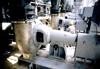
Many YM type pumps have been operating as circulation pumps
for desulfurizers at thermal power plants. |
Automatic operation system with enhanced self-priming
For details, please refer to "Current Topics: Seawater Intake".
|
|
|
|
|
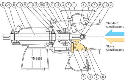
Structure
 |
|
|
Part name
|
|
1
|
Casing
|
|
2
|
Suction cover
|
|
3
|
Rear cover
|
|
4
|
Impeller
|
|
5
|
Liner ring
|
|
6
|
Liner ring (with protector)
|
|
7
|
Impeller ring
|
|
8
|
Rear plate
|
|
9
|
Bracket
|
|
10
|
Bearing case
|
|
11
|
Bearing cover
|
|
12
|
Bearing cover
|
|
13
|
Shaft
|
|
14
|
Impeller nut
|
|
15
|
Impeller washer
|
|
16
|
Sleeve
|
|
17
|
Seal ring
|
|
18
|
Gland
|
|
19
|
Gland packing
|
|
20
|
Cone roller bearing
|
|
21
|
Cylinder roller bearing
|
|
22
|
Casing packing
|
|
Specifications
|

|
Standard specifications
|
|
All parts which come into contact with liquid are made of metal and the
shaft is fully sealed to avoid contact with liquid.
|
|

|
Slurry specifications
|
|
The impeller, including the closed type, has a wear-resistant shape with
rear vanes at the coupling side. The liner ring with the protector prevents
wear of the suction cover caused by slurry blown against it.
The rear plate, which is exchangeable, is installed at the rear side of
the impeller to protect the casing from wear.
|
|

|
Shaft seal
|
|
Selection of the shaft seal most suitable for the type of liquid used and
site conditions is possible.
|
Example of shaft seal (Optional)
For details of Yokota Mechanical Seal, please refer to this page.
|
|
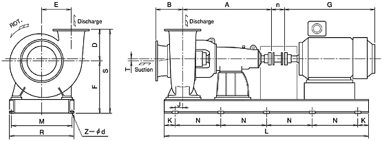
Selection chart & Outer dimensions
|
Selection chart
YM type
Model number explanation
XXXX-##@@-xP (**)
|
XXXX
|
: Pump type
|
|
##
|
: Suction/Discharge bore (cm)
|
|
@@
|
: Head classification
|
|
xP
|
: Electric motor pole number (2P, 4P, 6P, other)
|
|
(**)
|
: Electric motor output power (kW) at maximum performance (using normal
water at normal temperature)
|
|
|
|
Outer dimensions
YM type
|
|
 |
|
Model No.
|
Bore
Suction/
Discharge
|
Pump
|
Weight
(kg)
|
Motor
(Reference)
|
Base plate
|
|
A
|
B
|
D
|
E
|
F
|
T
|
S
|
Frame
No.
|
G
|
Z-d
|
K
|
N
|
L
|
M
|
R
|
n
|
J
|
|
YM-2510
|
300/250
|
660
|
300
|
320
|
130
|
425
|
20
|
745
|
260
|
225S
|
797
|
4-23
|
250
|
1100
|
1600
|
500
|
550
|
4
|
35
|
|
-2512
|
300/250
|
840
|
300
|
370
|
190
|
515
|
20
|
885
|
400
|
250S
|
880
|
6-23
|
150
|
900
|
2100
|
590
|
650
|
300
|
-65
|
|
-3020
|
300/250
|
660
|
320
|
365
|
125
|
480
|
15
|
845
|
320
|
225S
|
797
|
4-23
|
250
|
1100
|
1600
|
550
|
600
|
4
|
30
|
|
-3022
|
300/250
|
840
|
320
|
380
|
160
|
580
|
0
|
960
|
450
|
250S
|
880
|
6-23
|
150
|
900
|
2100
|
590
|
650
|
300
|
-70
|
|
-3030
|
300/250
|
1055
|
300
|
400
|
350
|
690
|
0
|
1090
|
800
|
250M
|
967
|
6-23
|
200
|
1000
|
2400
|
740
|
800
|
300
|
-20
|
|
-3520
|
350/300
|
1000
|
385
|
430
|
220
|
660
|
0
|
1090
|
800
|
280M
|
1083
|
6-23
|
250
|
1000
|
2500
|
690
|
750
|
300
|
10
|
|
-3530
|
350/300
|
1145
|
360
|
500
|
220
|
780
|
0
|
1280
|
1200
|
355L
|
1710
|
8-27
|
325
|
850
|
3200
|
1030
|
1100
|
300
|
100
|
|
-3540
|
350/300
|
1425
|
360
|
580
|
470
|
830
|
0
|
1410
|
1350
|
355L
|
1710
|
8-27
|
300
|
1000
|
3600
|
930
|
1000
|
300
|
50
|
|
-4040
|
400/350
|
1460
|
400
|
650
|
320
|
930
|
0
|
1580
|
1400
|
355L
|
1710
|
8-27
|
300
|
1100
|
3900
|
1030
|
1100
|
300
|
10
|
|
-4530
|
450/400
|
1480
|
450
|
600
|
300
|
880
|
25
|
1480
|
1900
|
355L
|
1710
|
8-27
|
350
|
1100
|
4000
|
1130
|
1200
|
300
|
35
|
|
-5550
|
550/500
|
1620
|
500
|
550
|
540
|
1000
|
0
|
1550
|
2700
|
400LL
|
1910
|
8-27
|
450
|
1200
|
4500
|
1130
|
1200
|
400
|
120
|
|
-5560
|
550/500
|
1740
|
450
|
650
|
550
|
1030
|
0
|
1680
|
3100
|
400LL
|
1910
|
8-27
|
425
|
1150
|
4300
|
1030
|
1100
|
400
|
110
|
|
-6060
|
600/550
|
2000
|
550
|
680
|
650
|
1185
|
0
|
1865
|
4500
|
500L
|
2300
|
10-33
|
300
|
1100
|
5000
|
1430
|
1500
|
500
|
-175
|
|
Note:
|
|

|
YM-2510 and YM-3020 do not adopt back-pullout structure, and dimensions
show those for flexible flanged-type couplings.
|
|

|
We manufacture to meet flange standards, such as JIS, API and ANSI, upon
request.
|
|

|
Outer dimensions refer only to electric motors at maximum motor output,
therefore there may be differences in outer dimensions. For details on
related dimensional outline drawings, please contact us.
|
|

|
For information on the automatic operation system using our enhanced self-priming
method, please contact us. We design and manufacture the control system
in accordance with operational conditions. (YM-2512, YM-3022 and YM-3520)
|
|
Specifications stated here may be subject to change without notice due
to product improvement.
|
>Back to Top
|
|
|