|
Resolving the concerns of agricultural water distribution
YOKOTA Constant Flow Regulator Valve (PAT.)
|
|
|
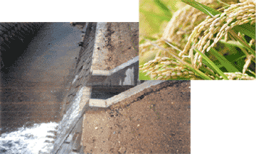
Water division works outlet and agricultural-use channel |
|
Water is indispensable for all agricultural crops. The critical role of
supplying only the necessary amount of water at the required time is performed
by agricultural irrigation systems.
In addition to traditional use of open channels, today we see increasing
use of pipeline irrigation that is a more rational form of water control
management and allows for more economic use of water resources.
We would like to present the YOKOTA Constant Flow Regulator Valve that
is being adopted more and more as a convenient control valve for pipeline
irrigation.
Agricultural-use water is taken from a dam or river, sent through a main
channel to where it is divided up and sent along branch lines. At the end
of the branch lines the water is then divided again for the agricultural-use
channels through which the water is supplied to the fields. For this reason,
the overall pipeline distance is quite long and there is a large variance
of pipe elevation due to the peaks and valleys the piping must traverse.
Supplying equal amounts of water to all fields in a stable manner under
these conditions is a challenging task. In order to ensure an even supply
of water, facilities called "water division works" are established
and it is here that flow rate control valves are installed and operate
so that water intake matches the flow rate specific to each water division
work.
|
|
|
|
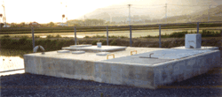
Water division works (flow rate control valve located underground)
|
|
By the way, in the past, the division of water to various fields was a
constant source of concern since nothing as useful as a flow rate control
valve existed.
For example, let's take a look at two large concerns of the past that have
caused numerous headaches:
|
(1)
|
If the source water level (pressure) changes or any other factor (such
as use of water through other water division works) causes a change in
the water intake pressure, the flow rate will soon change accordingly,
making it impossible to maintain the set flow rate. In the worst cases,
the flow rate can reach zero.
|
|
(2)
|
Agricultural-use water normally contains pebbles and refuse, and can even
have dried leaves, plastic bags, and even an occasional snake, all of which
can lead to clogging of conventional automatic control valves given their
delicate construction.
|
The YOKOTA Constant Flow Regulator Valve has been developed to resolve
these types of concerns.
First, let's take a look at the constant flow rate characteristics of the
Constant Flow Regulator Valve.
The flow rate shown along the vertical axis is securely maintained at a
constant value even if there is a change in the difference between the
primary side pressure P1 (inlet side) and secondary side pressure P2 (outlet side) as shown along the horizontal axis.
In addition to this secure constant flow rate characteristic, the YOKOTA
Constant Flow Regulator Valve is clog-resistant and, moreover, is highly
versatile as the set flow rate can be freely adjusted and, when water is
not needed at all, the valve can be completely shut.
How can one valve have all these capabilities? Before we explain how it
works, let's examine how the valve is used at some actual locations.
Constant Flow Regulator Valve used for discharge water distribution to
open channels
Constant Flow Regulator Valves were first installed at the Water Resources
Development Public Corporation (former name) in Gifu Prefecture in 1979.
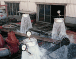
At that time, as seen in the photos below, the valves were installed as
discharge devices on the ends of piping and they were utilized as constant
flow rate discharge valves and also to reduce the pressure of high-pressure
water coming from higher elevations, such as that from dams.
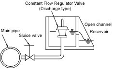
They were especially noteworthy for their compact structure, as seen in
the figure, allowing them to be installed with a minimum use of space.
|
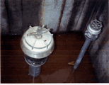
Discharge type Constant
Flow Regulator Valve
|
Constant Flow Regulator
Valve during discharge test
|
|
 |
|
|
|
|
In-line type Constant Flow Regulator Valve used for water distribution
to open channels
The lineup of Constant Flow Regulator Valves, including the in-line types
currently in use, was completed in 1986.
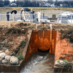
The photos below show a 400mm bore Constant Flow Regulator Valve installed
in a water division works of the Kasumigaura Canal of the Kanto Regional
Agricultural Administration. Due to this, a wide area of agricultural fields
in the Kanto Plains can be irrigated, allowing the valve to play a beneficial
role in producing bountiful crops.
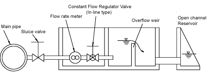
As shown in the figure, the valve is located in the middle of the piping,
enabling it to distribute water according to the set flow rate.
Because the Kasumigaura Canal must provide irrigation water for a large
area of agricultural fields in Ibaraki Prefecture, there are tens and even
hundreds of water division works locations, all requiring water simultaneously
during the irrigation season. The valve is able to ensure that no matter
how the pressure on the primary side changes, the flow rate from out of
the secondary side will remain exactly as set.
|
Constant Flow Regulator Valve
operating at the Kasumigaura Canal
|
Water division works
dividing water
|
|
|
|
|
|
|
 |
|
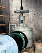
|
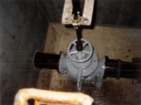
Constant Flow Regulator Valve with set valve key
and handle that can be turned from above ground (optional)
(Other electrically-operated functions available)
|
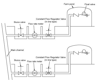
Constant Flow Regulator Valve used for farm pond water distribution
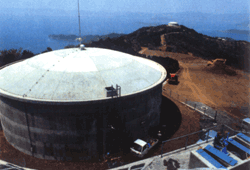
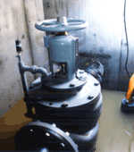
The photos below show a farm pond (agricultural-use water tank) located
at the top of a "mikan (Mandarin orange) hill" in Ehime Prefecture
and a 250mm bore Constant Flow Regulator Valve used for distributing water
to the pond.
Water used for irrigating the mikan orchards all over the hill is taken
from the main channel and brought to the top of the hill where it is stored
in the farm pond. In the past, it was extremely difficult to supply a uniform
amount of water to each hill with their varying altitudes. Now, however,
this task can be performed effortlessly thanks to the Constant Flow Regulator
Valve.
|
Farm pond on top of mikan hill
|
|
|
|
 |
|
|
Constant Flow Regulator Valve
performing water distribution to farm pond |
YOKOTA Constant Flow Regulator Valve (PAT.) features
|

|
The set flow rate is supplied at a stabilized rate regardless of charges
in primary pressure.
|
|

|
The set flow rate can be easily changed by handle operation. (Variable
constant flow rate type)
Furthermore, due to the valve structure that eliminates uneven loads on
the valve shaft, the handle can be operated with extremely light force,
making it extremely popular among older agricultural workers.
|
|

|
The simplified structures of the water passages ensure that they do not
become clogged with sand or other foreign material. Even if some large
debris gets stuck, it can easily be cleared out.
|
|

|
Maintenance is kept at a minimum due to the simple direct operation design
and lack of any complicated pilot control parts.
|
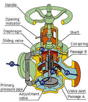
How is such precise constant flow rate control achieved?
Let's look at the figure and examine how the water flows.
The primary pressure water enters through the inlet and flows out in the
direction indicated by the arrow.
Chambers above and below the sliding valve are partitioned by the diaphragm
and the pressure of the upper chamber of the diaphragm is equivalent to
primary pressure P1 since the chamber is connected to the inlet via the primary pressure pipe.
On the other hand, since the lower chamber of the diaphragm (intermediate
chamber) is connected to the inlet via the throttle passage A, the chamber's
pressure Pd is slightly less than primary pressure P1.
Thus, the sliding valve lowers to a position where the differential pressure
(P1-Pd) is balanced against the coil spring force, adjusting the outlet passage
B so that water discharged from the outlet side remains at the preset flow
rate.
This is where the advantage of the Constant Flow Regulator Valve becomes
apparent.
If the primary pressure increases, increasing the rate of incoming water,
the passage resistance of passage A increases and the pressure differential
(P1-Pd) increases accordingly. When this occurs, the force pressing downward
on the sliding valve acts until the valve reaches a balanced position again,
and the outlet passage B is constricted so that the discharge flow rate
remains the same as before the primary pressure increased.
What do you think? Quite ingenious, isn't it? |
|
 |
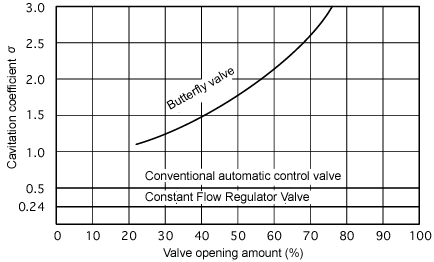
Cavitation coefficient
The cavitation coefficient is used as a standard for judging the performance
of flow rate control valves. The Constant Flow Regulator Valve has an excellent
coefficient value of 0.24 or less.
The figure below compares the cavitation coefficient of various valves.
As shown, a butterfly valve has a value of from 1 to 3 and a conventional
automatic control valve has a value of 0.5 so the excellence of the Constant
Flow Regulator Valve's cavitation characteristic is clearly understood.
|
|
|
Given this unique structure, the Constant Flow Regulator Valve is extremely
easy to use for water division works management, is beneficial for the
economic use of water resources, and can be utilized by those who strive
to create even more productive crops.
For details of this product, please refer to Constant Flow Regulator Valve UF series. |