|
 |
Multistage Self-Priming Pump
USM, UBM, MEF types (PAT.)
High head type with high performing self-priming mechanism
|
|
|
|
USM type (Driven by 4-pole motor):
|
Multistage centrifugal pump with self-priming mechanism
|
|
UBM type (Driven by 4-pole motor):
|
High head multistage centrifugal pump with self-priming mechanism
|
|
MEF type (Driven by 2-pole motor):
|
High head multistage centrifugal pump with self-priming mechanism
|
|

|
Outstanding self-priming performance
|
|
This pump is equipped with our patented self-priming (water-air separating)
mechanism, which displays outstanding self-priming power.
|
|
A large amount of incoming air can be separated and discharged during pumping.
Even if pumping becomes subject to suction or mixture of air due to fluctuations
of suction conditions, it continues pumping, constantly discharging air,
and restores normal pumping operation as soon as suction conditions return
to normal. Even continuous suction of air-containing water (i.e., gas-liquid
two-phase pumping) is possible.
|
|
Even if cavitation develops due to fluctuations of suction conditions such
as water level, temperature, or vacuum level on the suction side, this
pump can still continue its pumping operation. Therefore, this pump does
not require allowance for NPSH, and enables stable pumping operation even
under fluctuating suction conditions.
|
|
Due to its simple structure without any inlet check valve, it is robust
and easy to maintain. Moreover, there is no need for installing a foot
valve or an intermediate valve on the intake side under ordinary operating
conditions.
|
|

|
Self-balancing mechanism
|
|
With the crossover balancing mechanism for UBM types, and with the floating
disk type balancing mechanism originally developed by YOKOTA for the MEF
type, the axial thrust of its main shaft balances without axial movement
of the shaft. Therefore ordinary ball bearings can be adopted, and the
pump can be disassembled and reassembled very easily.
|
|

|
Large selection of materials
|
|
A wide variety of materials are available, including FC, SCS and YOKOTA's corrosion and wear resistant special stainless steel casting (YST), to meet the needs of various kinds of liquid.
|
Principle of self-priming
|
USM, UBM types
|
|
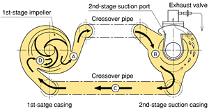
The self-priming mechanism consists of a 1st-stage casing with a smaller
passage and a larger passage forming a semi-double volute, and a 2nd-stage
suction casing with a 2nd-stage suction port.
|
|
|
|
|
1. Flow of circulation
|
|
During self-priming, the water discharged from passage A in the semi-double
volute returns to the impeller through passage B-C, and is discharged again
into passage A.
|
|
2. Removal of bubbles
|
|
This recirculation flow mixes the water and the air in the center with
intense vortex D within the impeller and discharges it into passage A.
|
|
3. Water-air separation and exhaust
|
|
The water-air mixture is led from passage A to chamber B and separated.
The separated air is discharged via an exhaust valve. The separated water,
not entering the multistage side through the 2nd-stage suction port, returns
to the 1st-stage casing to repeat the self-priming operation until separation
and exhausting are completed.
|
|
|
MEF type
|
|
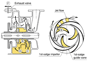
The self-priming mechanism consists of a 1st-stage impeller with a main
passage on the suction side and a self-priming passage on the back side,
guide vanes, and an exhaust valve.
|
|
|
|
|
1. Flow of circulation
|
|
When the pump starts to rotate, water in the pump circulates from D to
B, then to C.
|
|
2. Removal of bubbles
|
|
This circulating flow becomes an intermittent jet flow when it flows from
passage B, on the back side of the 1st-stage impeller, to passage C, mixing
the air with the water and carrying it away to passage C.
|
|
3. Water-air separation and exhaust
|
|
The water-air mixture is led from passage C to chamber D and is separated
by centrifugal force. The separated air goes through passage E and is discharged
via exhaust valve F. The separated water recirculates through D, B, and
then C, returning to the 1st-stage impeller to repeat the self-priming
operation.
|
|
4. Normal state
|
|
When self-priming is completed, water is pumped through main passage A
of the 1st-stage impeller, and fed to the multistage impellers through
passages C-D-G and C-E-G.
|
|
Applications
|
With the self-priming and pressurized discharge capabilities, these pumps
can be used even under extreme conditions. They can be used, for example,
as chemical pumps for liquids containing air, pumps for mixing air bubbles
in an aeration system (i.e., gas-liquid two-phase flow pumps), condensate
pumps, drain pumps, and pumps for extraction from sealed tanks.
|
|
Boiler feed
|
|
Transferring gas-containing liquid (gas-liquid two-phase flow)
|
|
Sealed (Vacuum) tank extraction
|
|
Water supply to high elevations
|
|
Pressurized water discharge
|
|
Seawater suction/transfer
|
|
Other
|
| Example applications and installations |
|
 |
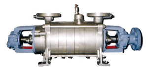 |
Seawater intake pump for the marine biological laboratory
(MEF type) |
|
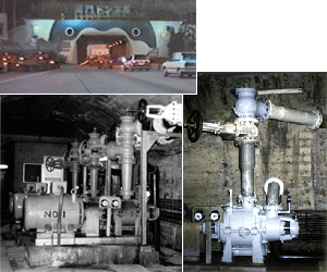
Seawater drain pumps under operation in Kanmon Tunnel
(USM type) |
There is detailed information about applications to seawater-related facilities.
Please refer to "Current Topics: Undersea Tunnel".
These are self-priming type pumps for suction pumping.
For non-self-priming types (for force pumping) with similar specifications,
please refer to
Multistage Centrifugal Pump MCF, MCH types.
|
|
|
Structure
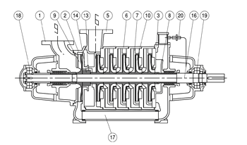
USM type
 |
|
Part name
|
Part name
|
|
1
|
1st-stage suction casing
|
13
|
Casing bush
|
|
2
|
1st-stage casing
|
14
|
Impeller spacer
|
|
3
|
2nd-stage suction casing
|
16
|
Shaft
|
|
5
|
Rear-final-stage casing
|
17
|
Crossover pipe
|
|
6
|
Multistage casing
|
18
|
Ball bearing
|
|
7
|
Multistage guide vane
|
19
|
Ball bearing
|
|
8
|
2nd-stage suction port
|
20
|
Exhaust valve
|
|
9
|
1st-stage impeller
|
|
|
|
10
|
Multistage impeller
|
|
|
|
|
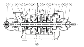
UBM type
|
|
Part name
|
Part name
|
|
1
|
1st-stage suction casing
|
11
|
Seal impeller
|
|
2
|
1st-stage casing
|
12
|
Seal impeller case
|
|
3
|
2nd-stage suction casing
|
15
|
Front-final-stage casing bush
|
|
4
|
Rear-stage suction casing
|
16
|
Shaft
|
|
5
|
Rear-final-stage casing
|
17
|
Crossover pipe
|
|
6
|
Multistage casing
|
18
|
Ball bearing
|
|
7
|
Multistage guide vane
|
19
|
Ball bearing
|
|
8
|
2nd-stage suction port
|
20
|
Exhaust valve
|
|
9
|
1st-stage impeller
|
|
|
|
10
|
Multistage impeller
|
|
|
|
|
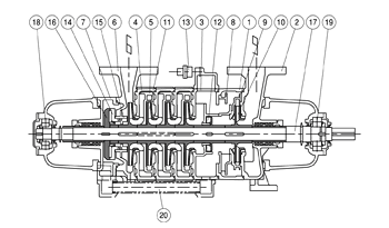
MEF type
|
|
Part name
|
Part name
|
|
1
|
1st-stage suction casing
|
11
|
Multistage impeller
|
|
2
|
1st-stage casing
|
12
|
Seal impeller
|
|
3
|
2nd-stage suction casing
|
13
|
Exhaust cover
|
|
4
|
Intermediate-stage casing
|
14
|
Balancing drum
|
|
5
|
Intermediate-stage guide vane
|
15
|
Balancing drum bush
|
|
6
|
Final-stage casing
|
16
|
Balancing disk
|
|
7
|
Balancing chamber cover
|
17
|
Shaft
|
|
8
|
1st-stage guide vane
|
18
|
Ball bearing
|
|
9
|
Guide vane
|
19
|
Ball bearing
|
|
10
|
1st-stage impeller
|
20
|
Balancing pipe
|
|
|
|
Selection chart & Outer dimensions
Specifications stated here may be subject to change without notice due
to product improvement.
|
>Back to Top
|
|
|