|
 |
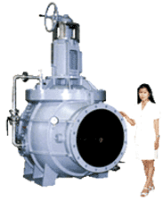
Constant Flow Regulator Valve
UF series (PAT.)
Easy flow rate setting and outstanding constant flow characteristics
|
|
|
|
ENEX'92
|
Received the prize for
outstanding product at the
'92 Energy Saving Exhibition |
|
|
|
| Patented in Japan, U.S.A., other |
|
Bore
|
25-600mm
|
|
Rated pressure
|
1MPa
|
|
|
>Selection & Dimensions |
Definitive model of constant flow regulator with variable flow rate setting
|

|
Excellent constant flow characteristics
|
|
With the built-in control function, the designated flow rate can be maintained
automatically regardless of changes in primary pressure, and the flow rate
can be set easily with the handle. It is an excellent variable constant
flow regulator.
|
|

|
Extremely low operating torque
|
|
Due to the unique balancing mechanism, the flow rate setting operation
can be done with low torque regardless of water supply pressure. This enables
application of a small electric actuator instead of manual operation, and even makes economical application of
a solar-powered system possible.
|
|

|
Simple direct-operation regulator valve
|
|
This simple direct-operation regulator valve does not use complicated pilot
valves and is therefore clog-resistant.
|
|

|
Cavitation characteristics
|
|
Due to the unique pressure reducing mechanism, the allowable cavitation
coefficient can be set extremely low.
|
|

|
Flow rate control characteristics
|
|
Lift type construction of the built-in adjustment valve enables nearly
linear performance in flow rate control.
|
|

|
High-performance
|
|
This automatic regulator valve has both constant flow control and flow
rate adjustment functions, so it is easy to handle and suitable for various
applications. To ensure durability and reliability, the main parts are
made of corrosion and wear resistant materials.
|
|

|
Demonstrated performance
|
|
Excellent performance as verified by the National Research Institute of
Agricultural Engineering of Japan.
|
Structure & Principle (PAT.)
|
1.
|
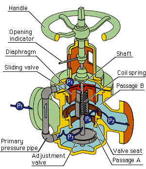
By adjusting the opening of the adjustment valve disk with the handle,
the required flow rate is set. Inlet pressure (primary pressure) P1 is adjusted to intermediate pressure Pd by the throttle resistance in passage A.
|
 |
|
2.
|
Inlet pressure P1 acts on the top of the diaphragm via the primary pressure pipe, and pushes
down the sliding valve.
|
|
3.
|
From the lower side, intermediate pressure Pd and working force of the coil spring push up the sliding valve until it
is balanced. Then it forms passage B and outlet pressure P2 is created by convergence.
|
|
4.
|
When inlet pressure P1 rises, the transmission of pressure P1, which acts on the top of the diaphragm, pushes down the sliding valve.
The sliding valve throttles passage B automatically until the sliding valve
can regain balance against intermediate pressure Pd and the force of the coil spring, so that the discharge amount is automatically
controlled.
According to this principle, the sliding valve is operated only by the
differential pressure between P1 and Pd as generated by the opening of the set adjustment valve, and therefore
the flow becomes constant at a rate proportional to the adjustment valve
opening regardless of the fluctuation of inlet pressure P1 or outlet pressure P2 as caused by the pressure fluctuation in the pipeline.
|
|
5.
|
When the adjustment valve is nearly closed, the adjustment valve disk and
the sliding valve disk are integrated via a shaft. Then pressure P1 against the adjustment valve disk from underneath balances with pressure
P1 against the diaphragm from above. This makes operation of the handle lighter
and facilitates the planning of mechatronics using a low-powered actuator.
|
Constant flow rate characteristics
|
|
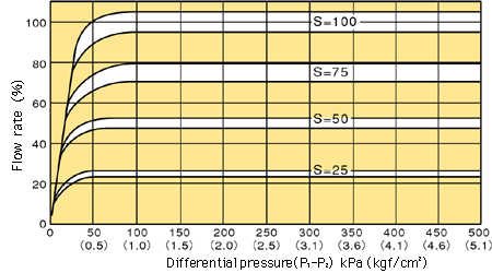
Fig.1 |
Flow rate stays at a constant value regardless of inlet pressure (primary
pressure) P1, outlet pressure (secondary pressure) P2, and their fluctuation.
Fig.1 shows the valve's ability to maintain a highly accurate constant
flow by following the adjustment valve disk opening {S denotes opening
(stroke %) in Fig.1}, regardless of the large variation of P1 and P2, or the large fluctuation of differential pressure (P1-P2). Further, with the linear characteristic (refer to Fig.2), the valve
is not influenced by various pipe conditions during operation, and works
with good control response and wide control range.
|
|
Constant flow rate characteristics at each set flow rate S
(adjustment valve opening %) |
 |
Flow rate control characteristics
|
|
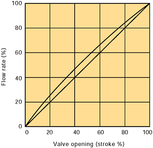
Fig.2 |
The YOKOTA Constant Flow Regulator Valve has a lift type construction,
which shows superb characteristics as a flow rate adjustment valve. Fig.2
shows performance close to the ideal linear characteristic parallel to
a 45 degree diagonal line.
|
|
 |
Cavitation characteristics
|
|
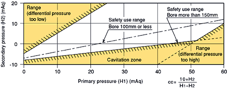
Fig.3 |
The allowable cavitation coefficients (cc) for the YOKOTA Constant Flow
Regulator Valve are:
With a bore less than 100mm: cc=0.45
With a bore more than 150mm: cc=0.24
As a result, the range in which the valve can be used safely, including
the allowable differential pressure range, can be set extremely wide as
shown in Fig.3. |
|
 |
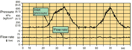
Fluctuation of inlet pressure and constant flow rate characteristics
|
Fig.4
|
|
|
Example applications
|
|
|
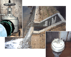
For agricultural irrigation
|
|
Water distribution to open channel
In-line type, Discharge type
|
|
|
|
|
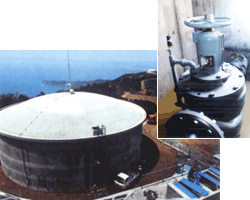
Water distribution to farm pond
|
|
|
|
|
|
For industrial use
|
|
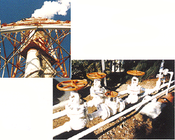
|
|
Funnel flushing system
|
|
|
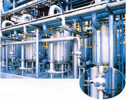
|
|
Water treatment system
|
|
|
|
|
|
For construction
|
|
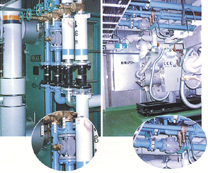
|
|
Large scale local heat supply system
|
|
|
|
|
|
|
For waterworks
|
|
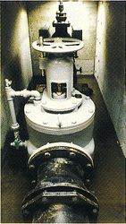 |
|
Harbor water supply facility
|
|
|
|
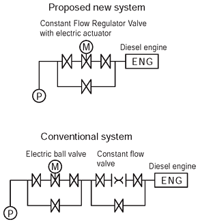
YOKOTA's proposal for economical piping units
Cost reduction in piping units is possible by using the YOKOTA Constant
Flow Regulator Valve.
For example, when supplying cooling water to the engines at rainwater drainage
plants, a piping system with an electric ball valve unit and a constant
flow valve unit set in a series is generally used.
But, it is possible to simplify this system into a single unit by using
the YOKOTA Constant Flow Regulator Valve.
This is because the YOKOTA Constant Flow Regulator Valve not only has a
function to control constant flow, but also functions to adjust the required
flow rate from the outside and to shut off the flow.
(Example) Comparison with a conventional system when cooling 1050HP engines.
(Calculated by the user)
1. Cost: Approx. 50% reduction
2. Space for installation: Approx. 50% reduction
3. Adjustment of flow rate is possible at installation site
|
|
Piping examples
|
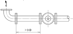
Installation in horizontal piping is standard.
Please contact us about installation in vertical piping.
|
|
1.
|
Standard piping example
|
|
(1)
|
It is not necessary to install a straight pipe at the rear of the Constant
Flow Regulator Valve.
When install a gate valve at the front of the Constant Flow Regulator Valve,
install a straight pipe as shown.
If you plan to install a flow meter, please install the designated straight
pipe.
|

D=Nominal bore
|
|
(2)
|
Install a piping within an angle of +/-3 degrees.
|
|
|
2.
|
When there is a bent pipe on the inlet side:
|
|
(1)
|
When the bent pipe is parallel to the valve shaft:
It is not necessary to install a straight pipe at the front or the rear
of the valve.
|

|
|
(2)
|
When the bent pipe is perpendicular to the valve shaft:
Install a straight pipe as shown.
|
D=Nominal bore
|
|
|
| UF series lineup / Selection charts & Outer dimensions |
Type
Flange standard
|
Usage examples
Bore (Nominal bore A)
|
Material
Valve case/
Main parts
|
Drive method
|
|
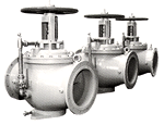
UFS type
In-line type
JIS 10K,
Waterworks
standard
|
|
Distribution and supply of agricultural, waterworks, industrial and river
water
Bore 50-600mm
|
SCS/SCS
FC/SCS
|
Manual
Electric actuator (∗)
Solar power (∗)
|
|
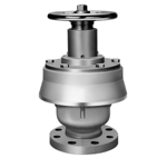
UFT type
Upward discharge type
JIS 10K,
Waterworks standard
|
|
Distribution and supply of agricultural, waterworks, industrial and river
water
Bore 50-150mm
|
SCS/SCS
FC/SCS
|
Manual
|
|
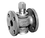
UFF type
In-line type
JIS 10K FF
|
|
Waterworks, air conditioning, local heat supply system, and liquid for
industrial use
Bore 25-50mm
|
SCS/SCS
|
Manual
Electric actuator (∗)
|
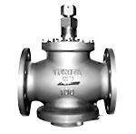
|
UFN type
In-line type
JIS 10K FF
|
|
Waterworks, air conditioning, local heat supply system, and liquid for
industrial use
Bore 65-150mm
|
SCS/SCS
FC/SCS
|
Manual
Electric actuator (∗)
|
|
Note:
|
|

|
(∗) denotes optional accessories.
|
|

|
For details of electric actuator drive and solar power drive, please refer
to this page.
|
|

|
Constructions of UFF type and UFN type differ slightly.
|
|

|
We also manufacture valves with other bore or primary pressure not listed
above upon request. Also a wide variety of materials are available, such
as YOKOTA's duplex type stainless steel YST130N with high corrosion resistance. Please inquire.
|
 |
For special liquids, please contact us. |
|

|
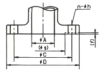
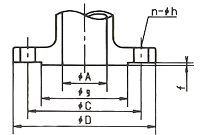
Flange dimensions are based on JIS standard. |
Flange standard dimensions
|
Standard JIS 10K FF type
|
Waterworks standard
|
|
|
Nominal
bore
A
|
JIS 10K, JIS B2239
|
Waterworks standard, JIS B2062
|
|
D
|
C
|
n-h
|
Bolt
|
(f)
|
(g)
|
D
|
C
|
n-h
|
Bolt
|
(f)
|
(g)
|
|
25
|
125
|
90
|
4-19
|
M16
|
1
|
67
|
Based on JIS 10K
|
|
32
|
135
|
100
|
4-19
|
M16
|
2
|
76
|
Based on JIS 10K
|
|
40
|
140
|
105
|
4-19
|
M16
|
2
|
81
|
Based on JIS 10K
|
|
50
|
155
|
120
|
4-19
|
M16
|
2
|
96
|
Based on JIS 10K
|
|
65
|
175
|
140
|
4-19
|
M16
|
2
|
116
|
Based on JIS 10K
|
|
80
|
185
|
150
|
8-19
|
M16
|
2
|
126
|
211
|
168
|
4-19
|
M16
|
3
|
125
|
|
100
|
210
|
175
|
8-19
|
M16
|
2
|
151
|
238
|
195
|
4-19
|
M16
|
3
|
152
|
|
125
|
250
|
210
|
8-23
|
M20
|
2
|
182
|
263
|
220
|
6-19
|
M16
|
3
|
177
|
|
150
|
280
|
240
|
8-23
|
M20
|
2
|
212
|
290
|
247
|
6-19
|
M16
|
3
|
204
|
|
200
|
330
|
290
|
12-23
|
M20
|
2
|
262
|
342
|
299
|
8-19
|
M16
|
3
|
256
|
|
250
|
400
|
355
|
12-25
|
M22
|
2
|
324
|
410
|
360
|
8-23
|
M20
|
3
|
308
|
|
300
|
445
|
400
|
16-25
|
M22
|
3
|
368
|
464
|
414
|
10-23
|
M20
|
4
|
362
|
|
350
|
490
|
445
|
16-25
|
M22
|
3
|
413
|
530
|
472
|
10-25
|
M22
|
4
|
414
|
|
400
|
560
|
510
|
16-27
|
M24
|
3
|
475
|
582
|
524
|
12-25
|
M22
|
4
|
466
|
|
450
|
620
|
565
|
20-27
|
M24
|
3
|
530
|
652
|
586
|
12-27
|
M24
|
4
|
518
|
|
500
|
675
|
620
|
20-27
|
M24
|
3
|
585
|
706
|
639
|
12-27
|
M24
|
4
|
572
|
|
600
|
795
|
730
|
24-33
|
M30
|
3
|
690
|
810
|
743
|
16-27
|
M24
|
4
|
676
|
|
Note:
|
|

|
We manufacture valves with RF flanges (dimensions f, g ) for JIS 10K pipe
flanges upon request.
|
|

|
The flange thickness is based on our standard.
|
|
>Back to Top |
|
|