|
Common specifications for Pilot-Type Regulator Valves
|

|
Flange standard:
|
JIS 10K, JIS B2062 Waterworks standard
|
|

|
Material:
|
FC, FCD, SCS/SCS
Besides the above, a wide variety of materials are available, such as YOKOTA's duplex type stainless steel YST130N with high corrosion resistance.
|
|

|
Applicable liquid:
|
Various liquids at temperatures of 0-70 degree C (Please inquire for special
liquids.)
|
|

|
Cavitation characteristics:
|
The allowable cavitation coefficients (cc) are:
With a bore less than 100mm: cc=0.45
With a bore more than 150mm: cc=0.24
For details, please refer to this page.
|
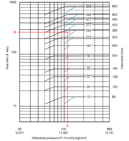
Common selection chart for Pilot-Type Regulator Valves

|
|
|
How to use the selection chart
|
|
Plot point C with x-axis value A and y-axis value B, where A is a planned
differential pressure between the front and the rear of the valve, and
B is a planned flow rate.
Then select a valve with a bore size line immediately above point C.
In the example on the left, the following valves are selected.
|
Standard type (shown by black lines)
|
| 350mm bore |
|
Constant flow regulation type (shown by blue lines)
|
| 400mm bore |
|
|
Note:
|
|

|
The selection chart is based on the maximum flow speed of 3m/sec. If a
planned maximum flow speed exceeds this level, please contact us.
|
|

|
The minimum flow rate while in continuous use should be more than 10% of
the maximum flow rate.
|
|

|
|
∗
|
Inspection window is furnished on valves with a bore of 150mm or more.
|
|
∗
|

|
shows an orifice added for over-discharge cutoff function.
|
|

|
shows a horizontal shaft type butterfly valve (optional) installed in place
of the orifice.
|
|
∗
|
The size of short pipes that are attached to the front and the rear of
the orifice or the butterfly
valve should be same as a valve bore.
|
|
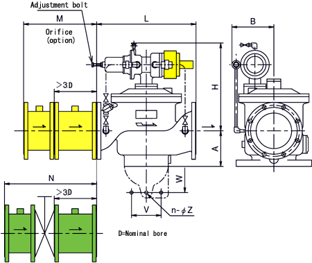
Common outer dimensions for Pilot-Type Regulator Valves
|
Model No.- Bore
|
Outer dimensions
|
Mounting dimensions
|
Orifice
(Note)
|
Weight of
main body
(kg)
|
|
L
|
A
|
B
|
H
|
V
|
W
|
n-Z
|
M
|
N
|
|
UFS@-080
|
280
|
95
|
235
|
330
|
-
|
-
|
-
|
436
|
479
|
80
|
|
100
|
350
|
127
|
230
|
380
|
-
|
-
|
-
|
496
|
545
|
90
|
|
125
|
420
|
145
|
260
|
440
|
-
|
-
|
-
|
591
|
644
|
130
|
|
150
|
450
|
153
|
230
|
470
|
-
|
-
|
-
|
666
|
719
|
170
|
|
200
|
600
|
220
|
285
|
545
|
-
|
320
|
2-23
|
826
|
883
|
270
|
|
250
|
700
|
250
|
440
|
585
|
-
|
500
|
2-23
|
986
|
1051
|
400
|
|
300
|
800
|
295
|
440
|
600
|
-
|
440
|
2-23
|
1146
|
1221
|
510
|
|
350
|
900
|
305
|
370
|
700
|
-
|
480
|
2-23
|
1306
|
1381
|
590
|
|
400
|
1000
|
320
|
385
|
800
|
-
|
660
|
2-25
|
1476
|
1575
|
800
|
|
450
|
1100
|
450
|
540
|
970
|
-
|
600
|
2-27
|
1626
|
1737
|
1200
|
|
500
|
1200
|
450
|
540
|
970
|
-
|
600
|
2-27
|
1786
|
1910
|
1300
|
|
600
|
1400
|
500
|
580
|
1000
|
-
|
700
|
2-27
|
2126
|
2277
|
2200
|
Note:
An orifice or a butterfly valve is installed when flow rate control function
is required.
The above "M" indicates the dimension of the orifice, and "N"
indicates the dimension of the butterfly valve unit (optional) installed
in place of the orifice.
If a butterfly valve is installed, short pipes are attached to the front
and the rear of the butterfly valve as shown in the above drawing.
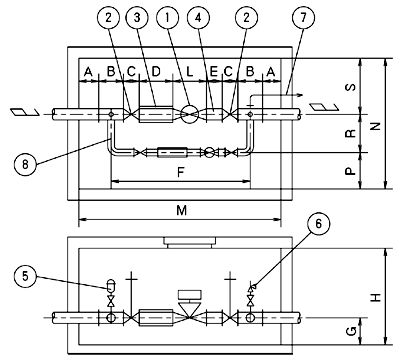
Installation example for the Constant Pressure Valve (reference)
|

|
|
Part name
|
|
1
|
Constant Pressure Valve
|
|
2
|
Sluice valve
|
|
3
|
Flexible joint
|
|
4
|
Short pipe
|
|
5
|
Air valve and safety valve
|
|
6
|
Safety valve (with bore of 1/2 the main valve bore or more)
|
|
7
|
Drain pipe
|
|
8
|
By-pass piping unit
|
|
|
|
Model No. - Bore
|
Installation and piping dimensions
|
|
A
|
B
|
C
|
D
|
E
|
F
|
L
|
P
|
R
|
S
|
M
|
N
|
G
|
H
|
|
UFSP- 80
|
270
|
320
|
240
|
400
|
240
|
1720
|
280
|
500
|
700
|
500
|
2580
|
1700
|
300
|
1700
|
|
100
|
275
|
360
|
250
|
400
|
300
|
1910
|
350
|
500
|
700
|
500
|
2820
|
1700
|
350
|
1700
|
|
125
|
280
|
370
|
260
|
450
|
375
|
2135
|
420
|
500
|
700
|
500
|
3065
|
1700
|
350
|
1700
|
|
150
|
290
|
380
|
280
|
450
|
450
|
2290
|
450
|
500
|
700
|
600
|
3250
|
1800
|
355
|
1800
|
|
200
|
300
|
400
|
300
|
600
|
600
|
2800
|
600
|
500
|
700
|
600
|
3800
|
1800
|
420
|
1900
|
|
250
|
300
|
460
|
380
|
750
|
750
|
3420
|
700
|
500
|
700
|
700
|
4480
|
1900
|
450
|
1900
|
|
300
|
300
|
480
|
400
|
900
|
900
|
3880
|
800
|
500
|
700
|
700
|
4960
|
1900
|
500
|
2000
|
|
350
|
300
|
720
|
430
|
1050
|
1050
|
4580
|
900
|
600
|
800
|
800
|
5900
|
2200
|
550
|
2200
|
|
400
|
300
|
820
|
470
|
1200
|
1200
|
5160
|
1000
|
600
|
850
|
800
|
6580
|
2250
|
580
|
2400
|
|
450
|
300
|
880
|
500
|
1350
|
1350
|
5680
|
1100
|
600
|
900
|
900
|
7160
|
2400
|
750
|
2800
|
|
500
|
300
|
960
|
530
|
1500
|
1500
|
6220
|
1200
|
600
|
1000
|
900
|
7780
|
2500
|
750
|
2900
|
|
600
|
300
|
1100
|
560
|
1800
|
1800
|
7220
|
1400
|
600
|
1100
|
1000
|
8920
|
2700
|
800
|
2900
|
|
|
Note:
|
|
To simplify installation, a unit with the valve preinstalled in a box culvert
can be provided. Please inquire.
|
|
Notes on piping and handling
|
|

|
Installation in horizontal piping is standard. Please contact us about
installation in vertical piping.
|
|

|
It is not particularly necessary to install a straight pipe at the front
or the rear of the valve, however sharp deflection of flow directly before
the main valve should be avoided as much as possible.
|
|

|
Sluice valves for maintenance and inspection should be provided at the
inlet and the outlet sides of the valve.
|
|

|
A strainer should be installed at the intake of the pipeline or the inlet
side of the valve.
|
|

|
For a pump feeding system, a high speed air valve should be installed in
any line where air may enter during stoppage of the pump.
|
|

|
For the Constant Pressure Valve, safety valves (with a bore of 1/2 the
main valve bore or more) should be installed at the inlet and the outlet
sides, and drain pipes should be installed from the safety valves to the
discharge outlet. Our reliable YOKOTA Safety Valves are most suitable for
this purpose.
|
|

|
For the Liquid Level Regulator Valve, there may be a time lag between closure
of the ball tap and subsequent closure of the main valve, which should
be considered in deciding the set water level. If you need more help, please
contact us.
|
Specifications stated here may be subject to change without notice due
to product improvement.
|